
About the Alicianrone
Some time in mid-late 2022, a where I was in the low of the keyboard Dunning-Kruger valley and didn’t realize it, I made the very unwise decision to try and design a keyboard. Equipped with KLE and Fusion360, my hands quickly got working on what I hoped would be a breakthrough product in the space, a so-called 1800 Arisu.
Inspiration
By the time the idea of making my own keyboard from scratch came up, I had two things on my mind immediately: GMK Arch (i used arch btw) and Keychron’s (at the time) freshly-released Q10, a blend of the Arisu layout and 75%. GMK Arch was a rather impulse purchase I bought from the now long-gone Mechs & Co and that purchase, in the spirit of Arch, inspired me to created my own whole keyboard from scratch, tailored to whatever the heck purpose I wanted. Unfortunately, since that purchase, it has faded to hell and back because of WS2 legends and accent modifiers, so it’s kinda ruined for me, but the spirit of the process stays. Mostly because I have been stuck in sunk-cost hell for the better part of 2 years.
Development
Development of the project, as my first project, was extremely rocky, hence the 2 and a half year time of on-and-off progress and constant scrapping of old ideas in favor of more sane and feasible design choices. If you plan to get yourself involved on a project like this, absolutely, absolutely, join the Keyboard Atelier Discord. I didn’t because I am not a fan of joining Discords that could very easily be online forums instead of gating information behind a private software like Discord, but that’s just me. Had I joined earlier (or, pretty much at any point in the process), I could have prevented many of the mistakes that I thought were uncurable but instead only had a couple of (very helpful) people kind of giving advice at a glance.
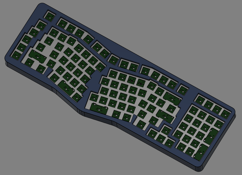
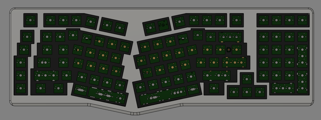
PCB
The first thing that was built, which is hopefully obvious, is the PCB. Having a guarantee that your switches and keycaps won’t interfere with each other and knowing the exact size of case needed is the most important part. Keep in mind, I had basically no electronics knowledge by this point. I could tell you about basic logic gates but otherwise, I had no (and probably still very little) electronics knowledge. At the time of starting this project, most PCB commissions had prices in the 4 digits, for what reason I don’t know, but it’s my knowledge that this kind of thing has become far more approachable.
So, I was stuck learning on my own if I wished to avoid shelling out more money than I was worth. That was when I came across ai03’s (very outdated) PCB guide. It’s not a very relevant guide parts-wise anymore, but it will do more than enough to get you a functional PCB and not much more. Eventually I was able to create a very scuffed design based off eye-balling. The biggest problem is probably the way the original Alice was made where the measurements seem debatably arbitrary and without hyper-analyzing it is hard to perfectly recreate from scratch, which in turn led to me doing some pretty cursed things in KiCad and creating a PCB with measurements as precise as 3 decimal points, which is a big no-no unless it’s an even fraction like 1/8 or 1/16.
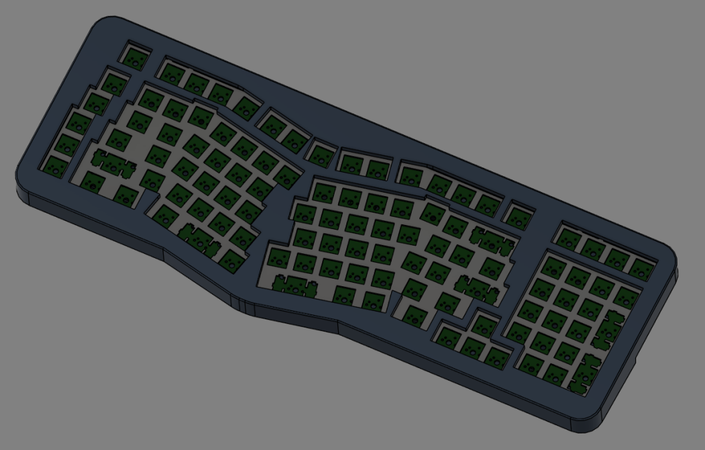
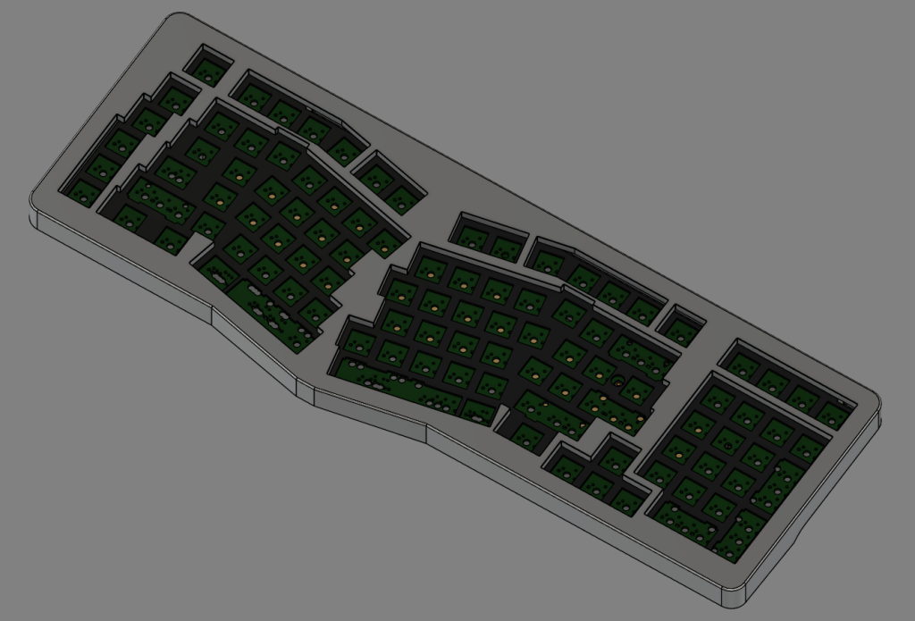
The PCB in its original form was stuck to one fixed layout based on my initial idea to add as many keys as possible, but eventually in a later revision this was formatted to instead cover a lot of familiar options, as well as some debatably overkill options like the various bottom row and spacebar options, and the rare 1.25u enter to allow a mock-up of ISO Enter on an Alice-style board. All-in-all, the idea is to be as flexible as is reasonable in the fashion of an overkill Arch user (btw). If I had to improve the design, it would surely be to include a cheaper and stronger MCU like the RP2040, but I’m not quite comfortable yet to start randomly swapping out parts without understanding the consequences.
Case
The case absolutely saw the most development as time went on, going through a total of 6 revisions. When going into it, I simply did not have any idea what I was doing to an exact extent. Prior to messing with Fusion360, I had only toyed around with CAD very mildly in my high school engineering class, so I had a grasp of what functions did what, but no magic snafu that allowed me to create the brilliant designs I had seen at the time (and even still some designs completely go over my head in how they were created). When it came to the first iteration, I was very much going off my at-the-time flawed idea of how a good keyboard was designed, considering how my best boards at the time were a Tofu and my Keychron boards. My first instinct was to try something more industrial looking, something that I thought was unique, something stable, and, well, out came something that looks like a janky LEGO® piece (please spare me, lawyers). The internals were incredibly scuffed, being a lowered platform like a living room in the 80s, and four posts that I guess you were just supposed to pray to line up correctly to with the daughter board? Also present through the first couple designs is a lack of internal weight, as I guess I just wasn’t confident in implementing a weight design? I’m not sure my hesitation for so long, but eventually I manned up and just did it later on.
Shortly after realizing my horrible mistake, I quickly began drafting a new way to make a rev 2. By this point, I had studied my Keychron boards a little closer and had seen the popular release of some still-relevant boards like the Mode Sonnet. Instead of being a completely flat bottom and weird sides, I finally started embracing letting the case have a bit of an overhang- probably too much of an overhang, though. I was also still stuck on having only four gasket tabs which I’m fairly certain to this day would have created issues in not having enough stability without a mount somewhere in the middle. Also notable is the kind of ugly seam that very obviously shows where the top case shrouds over the bottom case, with there being an overhang, as well as the angled front to the bottom case that much more closely mimics what Keychron’s cases look like. My hubris specific to this keyboard (as the internals are largely the same) probably would have been the lack of consideration of the board’s center of gravity and the fact the flat portion of the bottom case was cut back so short, so tipping would have probably been a very common issue. At least it looked a bit more like a custom keyboard? By this point I had also bought myself a prototype PCB before even having all my eggs in the basket, kind of a shortsighted decision.
Pretty quickly after the conclusion of rev 2, I started rev 3 to make something a little more simple and less jankily created (mostly in the side profile and that huge, leaning overhang). What came out starts to more resemble what I have in my current design and I think is where I started better learning how to reason out my design philosophy and make something that isn’t overly engineered yet still makes a striking design. By this point, I start to experiment with a slightly more traditional USB port design, albeit still kind of scuffed as I’m using a whole chamber meant for it instead of a proper channel. Similar to the previous design, I fear that I didn’t push the bottom case close to the back enough to make it less difficult to tip with its more front-heavy design. But again, we’re getting there.
I ended up sitting on rev 3 for a while, but eventually after getting into some better sounding boards like the Brutal 65V2 and the Bakeneko, it reinvigorated some energy to try again with nailing the “simple but effective” design I’d come to enjoy more on a rev 4. This time around, I started playing with better matching the top case and bottom case side contours instead of disjointing them in the name of “unique” design, with probably too obvious inspiration from the Sonnet. The bottom case ended up coming out far more like the Brutal 65V2 than I had really intended, but it basically is just a Brutal bottom case in the shape of an oversized Alice board. It did come with the opportunity to thin the bezels on the case a bit, though. At first I had tried a more concave taper for the “wedge” of the case, which was both not really that appealing and also only complicated adding the USB port. On that note, we finally have a proper daughterboard channel! The screw placements are also still definitely far too close to the edge to be safe. I’m also not too sure about the feet placement, either. By this point I had also found myself a place to get plates made at a local waterjet company, and while they were okay, once again I was jumping the gun too early (and got them made in 6063 instead of 5052).
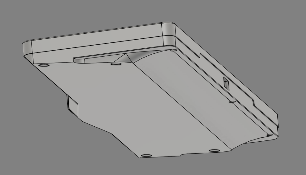
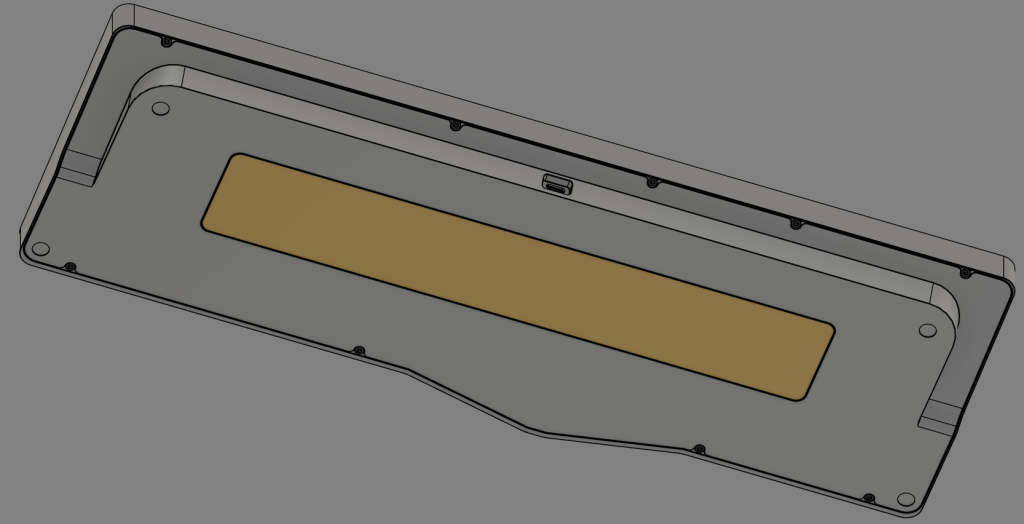
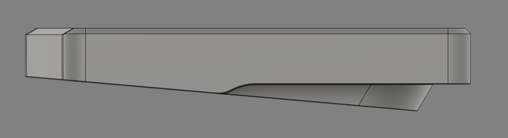
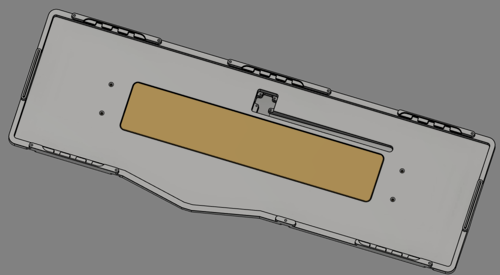
The rev 4 design sat for a while, probably the longest of all my designs. For a while I was simply stuck on how to improve the design until I finally got hands on with some actually better boards like the Milan and the Arc60 that I decided to finally start rev 5. The first important matter was to bring down the front height, as by this point all the designs were easily exceeding 20mm, often times landing towards 21-22mm or higher. After lots of min-maxing whatever was going on internally, I was eventually able to get just under 20mm at the main alphanumeric cluster, and I’m fairly certain the very tip of the lower alphas is under 18, but I haven’t checked as that part might just be cheating. Based on the length of the keyboard, I also finally realized I should probably have lowered the angle from 7° to 5° earlier, as it does look a lot more daunting and imposing when it’s so much taller. Also, we finally have a weight! Originally it was external only to hide the screws, but from my experience using the Milan, I also realized an internal weight would be valuable as well. So, I made a T-shaped hole so that the weight would be present both internally and externally. The only immediate flaw I can think of with this weight design is that light could peek through the top and bottom of the weight, but it shouldn’t be noticeable enough since the interior will be dark, anyway. You can also see the side profile beginning to take shape and is essentially where we’re at today with slightly less refinement than current. At this point, I would say we land something that goes between Derivative and Sonnet, with a weight more like you’d see out of a Fossil or the QK100. Otherwise, by this point I’d say most things were fleshed out, however between the really precise dimensions (down to .003mm last I recall) as a result of deriving off the PCB, the admittedly sub-par gasket design which also landed one near the spacebar, and the already pre-existing screw design making it hard to implement a top mount which I have quickly been converted to, it felt like I was just barely off the mark and the resolution was finally around the corner.
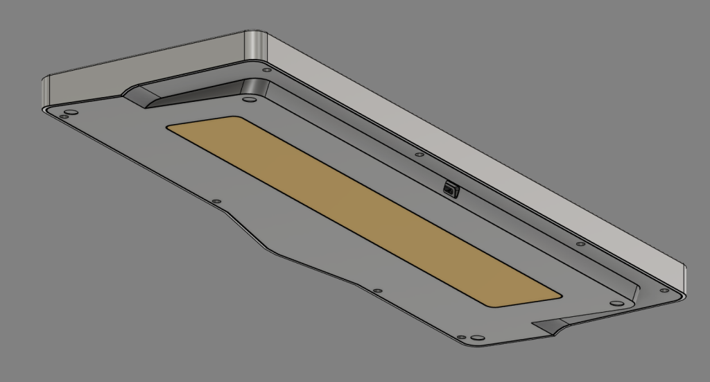
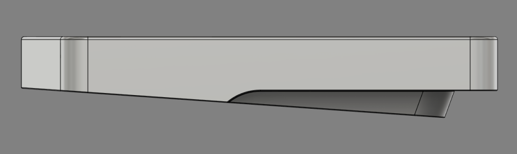
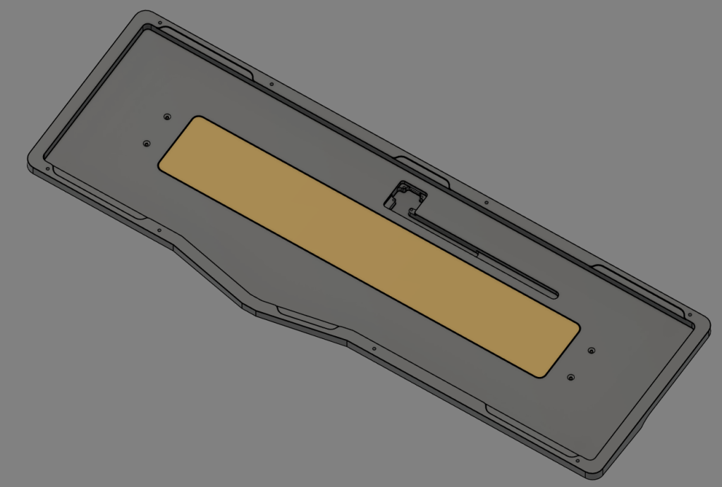
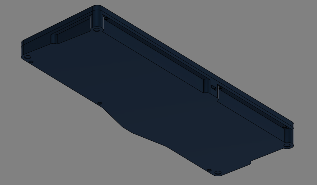
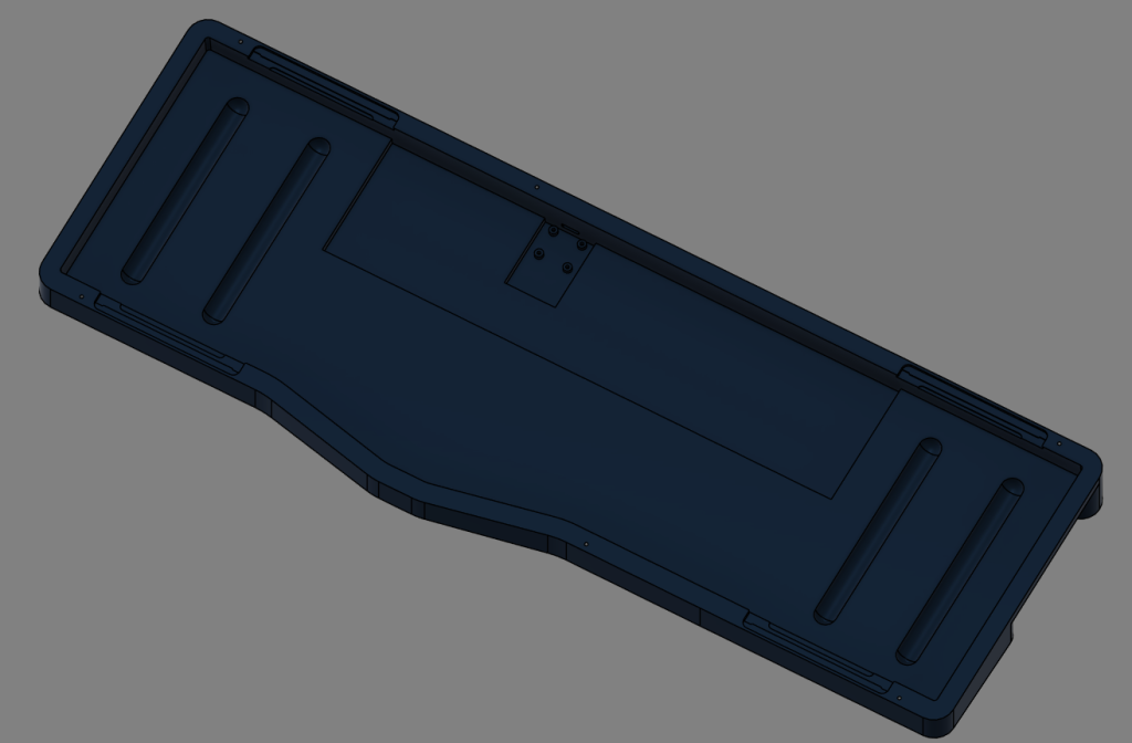
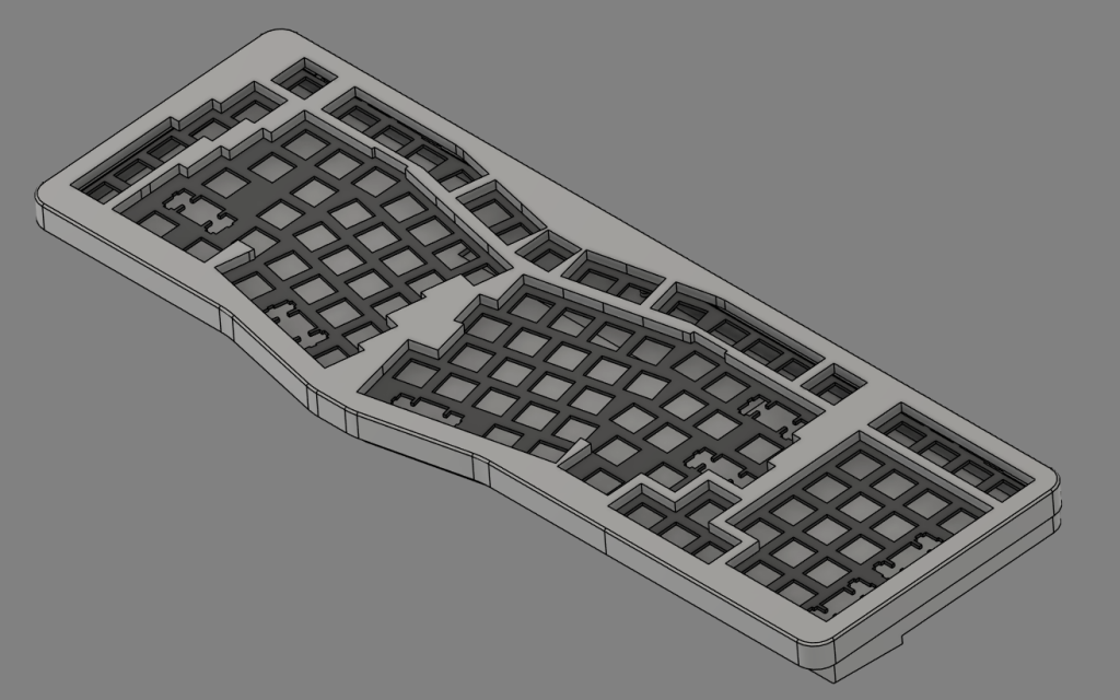
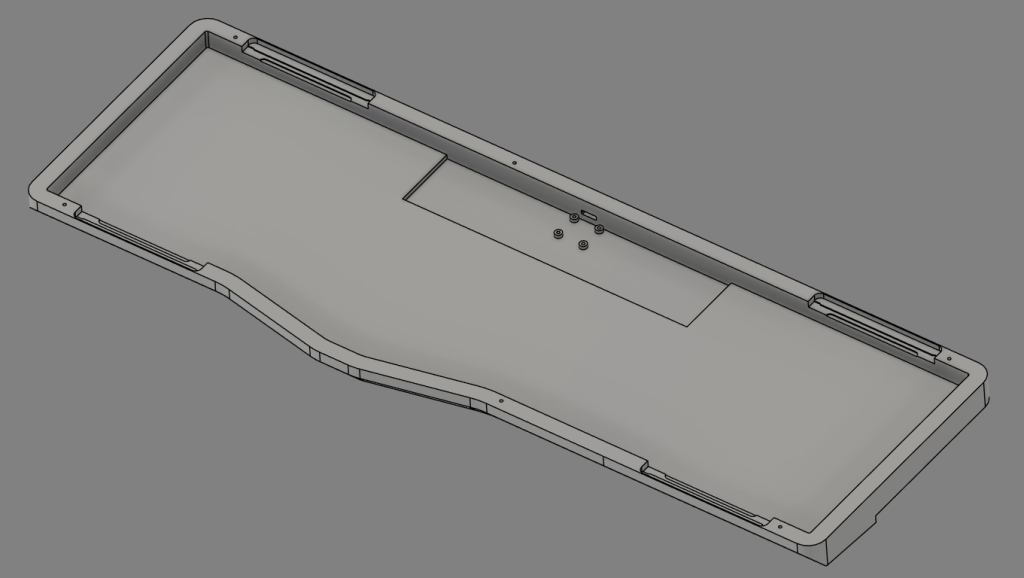
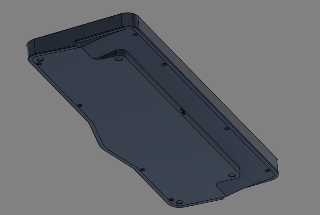
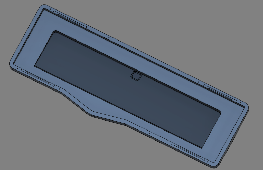
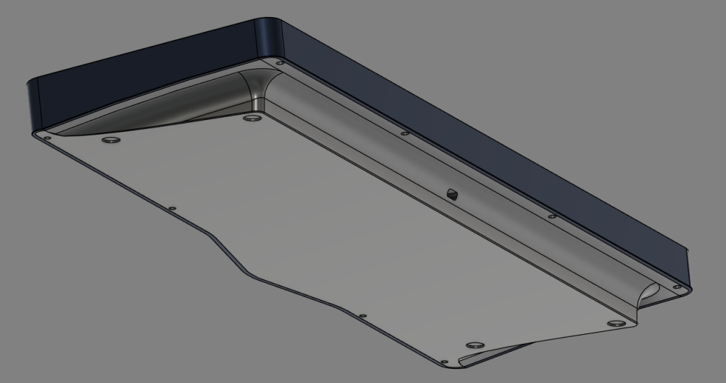
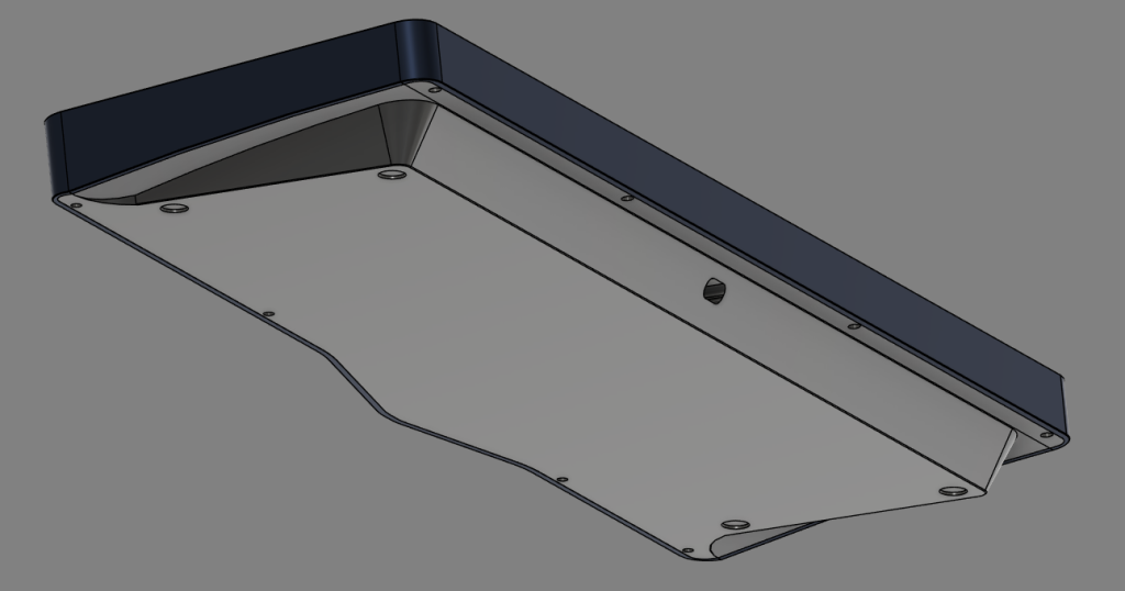
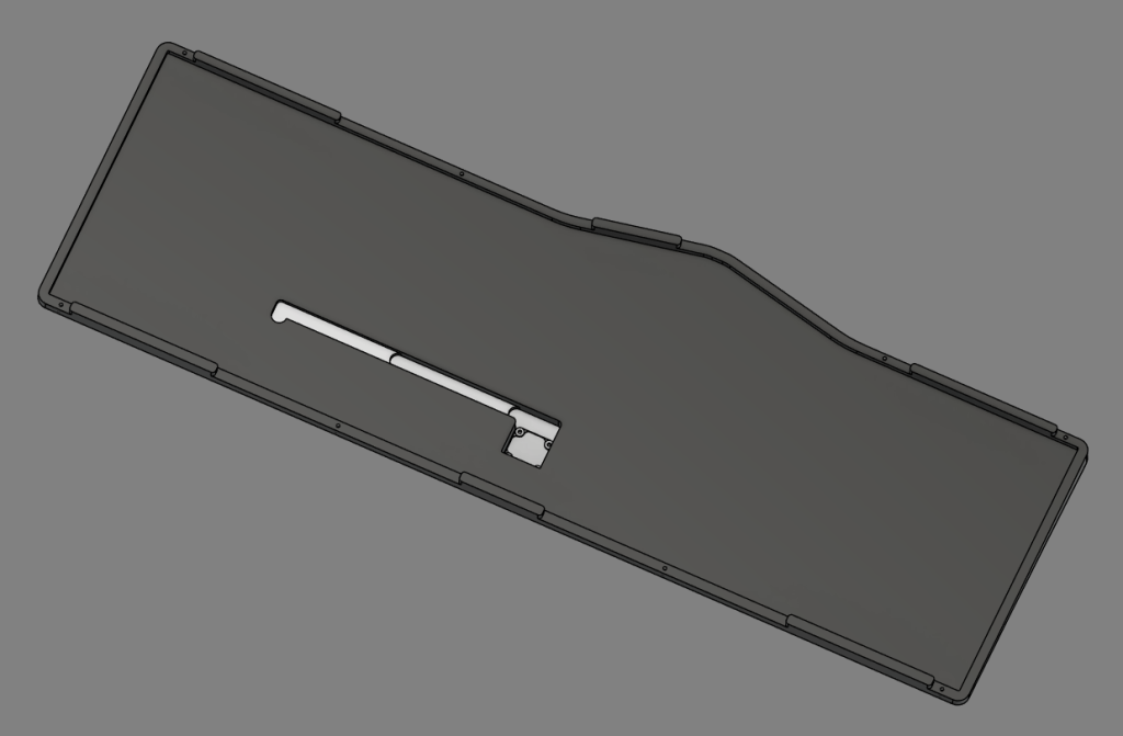
And that gets us to roughly April 2025. Once I found myself not particularly enjoying what I had made solely because I couldn’t do a top mount easily, as well as to make something with a nicer top side instead of the tiny fillet, it was time for rev 6. Continuing my inspiration from the Arc60 and my much more recently-acquired Frog Mini Leggera, I really wanted to make a cleaner chamfer top with that kind of fake front Cherry lip as something about it just looks appealing to me, making it shallower towards the front but otherwise even across the rest of the board. As previously mentioned, I wanted to implement a top mount, so this revision does that while also retaining the original gasket mount, though in a much more uniform implementation that instead of using multiple sizes of gaskets, uses only 50mm length gaskets. Along with this gasket implementation, knowing the pain of swapping between mounts, I also added a few divots along the parts the gasket would mount to to make it easy for a pair of tweezers to get underneath and hopefully more easily peel it off. By this point, you may ask: Why not silicone gaskets? Well, I hate silicone gaskets. While it’s true that their ease of attachment and replacement is unparalleled compared to poron, the sound character from silicone (especially sleeves) just ends up more thuddy and dull, and oftentimes a perfect fit can cause a lot of unwanted resonance. So, poron. Speaking of the mounts, I also brought back the Brutal-style bottom case where the gasket portions and screw mounts are raised to allow for less case contact in an effort to reduce case resonance, and because of this change, have also added two alignment slots to the sides. With this design the spacebar gasket is also removed, but a central gasket still remains above. Finally, the dimensions are tweaked so that now the entire case width and length should be even to .5mm for all the OCD enjoyers out there. The side curve also now very slightly curves in an S, but it’s very subtle. Would you believe me if I said I did this in a weekend? Or does it not count because I have worked on all the revisions prior to this? It’s no Bakeneko% speedrun, but still, I’m kinda proud I grinded this revision out as quick as I did.
Long-Term Support
And the best part? I want to open-source this board once I’m concluded with running this board once or twice. Immediately, I will be open-sourcing the plate and weight files for immediate customization and play with the materials. Further down the line, I would like to also try to make a 3-D printable version of this board to allow access to this design so that all you need is the proper filament, PCB (or handwire!) and daughterboard, brass inserts for screws, and you can make your own at home or for much cheaper. Furthermore, I would like to hope that this can remain as a starting-point resource for people and can use it to find inspiration for their own design, or even create derivative projects. Really: Once I see my design through, I will generally not mind what people do with it as long as all credit due is sent the right way and you’re not doing some messed up shit.